
The Digital Circuits whose sole purpose is to perform addition is known as Adders. The VHDL code for the Half Adder circuity is Further, this becomes the heart of digital electronics. Instead of only addition, these circuits are capable of handling various applications in digital circuits.To calculate the addresses and tables these circuits are preferred.These logic circuits are preferred in the design of calculators.The combination of half adder circuits leads to the formation of the Full Adder circuit.


It does not store any personal data.The applications of this basic adder are as follows The cookie is set by the GDPR Cookie Consent plugin and is used to store whether or not user has consented to the use of cookies. The cookie is used to store the user consent for the cookies in the category "Performance". This cookie is set by GDPR Cookie Consent plugin. The cookie is used to store the user consent for the cookies in the category "Other. The cookies is used to store the user consent for the cookies in the category "Necessary".

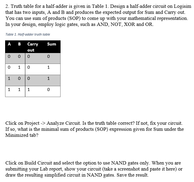
The cookie is set by GDPR cookie consent to record the user consent for the cookies in the category "Functional". The cookie is used to store the user consent for the cookies in the category "Analytics". These cookies ensure basic functionalities and security features of the website, anonymously. Necessary cookies are absolutely essential for the website to function properly. What can be used as component for Full Adder in structural style Modelling using VHDL?Īrchitecture structural of FAdder is component HA is Port ( A,B : in STD_LOGIC S,C : out STD_LOGIC) end component component ORGATE is Port ( X,Y: in STD_LOGIC Z: out STD_LOGIC) end component Next, we will declare all the signals in the circuit using the signal declaration statements. Cout is High, when two or more inputs are High. sum(S) output is High when odd number of inputs are High. Truth Table describes the functionality of full adder. The VHDL Code for full-adder circuit adds three one-bit binary numbers (A B Cin) and outputs two one-bit binary numbers, a sum (S) and a carry (Cout). Combining these two, the logical circuit to implement the combinational circuit of Half Adder is shown below….Half Adder Truth Table. If A and B are binary inputs to the half adder, then the logic function to calculate sum S is Ex – OR of A and B and logic function to calculate carry C is AND of A and B. In practice they are not often used because they are limited to two one-bit inputs. A half-adder shows how two bits can be added together with a few simple logic gates. Half adders are a basic building block for new digital designers.


 0 kommentar(er)
